The Installation and Use of Ball Valves
Description
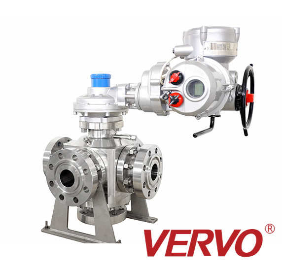
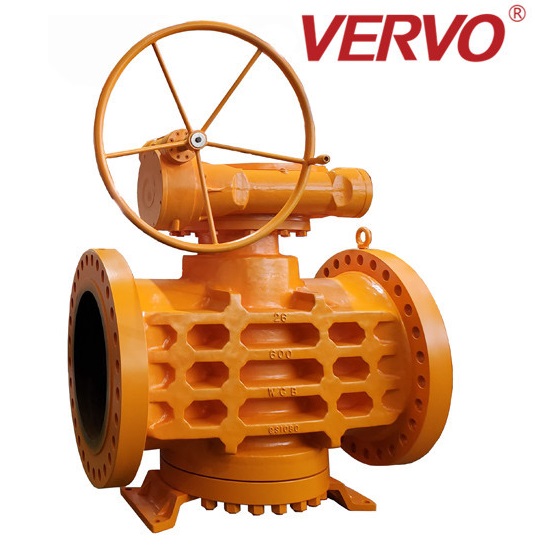
How to install the ball valve? What preparations should be made before installation? What should we pay attention to when using ball valves? The following Jiayi Valve will introduce the installation and use of ball valves in detail, hoping to help those engaged in the valve industry.
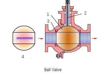
1. Ball 2. Valve stem 3. Sealing seat 4. The top sectional view of the ball
Preparation before installation of ball valves
1. The front and rear pipes should be coaxial, and the sealing surfaces of the two flanges should be parallel. The pipeline should be able to bear the weight of the ball valve, otherwise, the pipeline must be equipped with proper support.
2. Purge the pipeline before and after the valve, and remove the oil, welding slag and all other impurities in the pipeline.
3. Check the mark of the ball valve to find out that the ball valve is in good condition. Open and close the valve several times to verify its normal operation.
4. Remove the protective pieces on the connecting flanges at both ends of the ball valve.
5. Check the valve hole to remove possible dirt, and then clean the valve hole. Even tiny particles of foreign matter between the ball and the valve seat may damage the sealing surface of the valve seat.
Ball valves installation
1. Install the ball valve on the pipeline, and either end of the ball valve can be installed at the upstream end. The ball valve driven by the handle can be installed at any position on the pipeline. However, the gearbox or pneumatic ball valve should be installed vertically, that is, on the horizontal pipeline, and the driving device is above the pipeline.
2. Install a gasket between the valve flange and the pipeline flange according to the requirements of pipeline design.
3. The bolts on the flange should be tightened symmetrically, successively and evenly.
4. Connect the pneumatic pipeline (when the pneumatic driver is used).
Inspection of ball valve after installation
1. Operate the opening and closing ball valve of the driver several times, which should be flexible and free from stagnation, to confirm its normal work.
2. Check the sealing performance of the flange joint surface between the pipeline and the ball valve according to the requirements of pipeline design.
Use of ball valves
1. you must first find out that the upstream and downstream pipelines of the ball valve have indeed been depressurized before disassembly and disassembly.
2. Non-metallic parts shall be taken out of the cleaning agent immediately after cleaning, and shall not be soaked for a long time.
3. During assembly, the bolts on the flange must be tightened symmetrically, gradually and evenly.
4. Cleaning agent should be compatible with rubber parts, plastic parts, metal parts and working medium (such as gas) in the ball valve. When the working medium is gas, the metal parts can be cleaned with gasoline (GB484-89). Clean nonmetallic parts with purified water or alcohol.
5. Each single ball valve part decomposed can be cleaned by dipping. The metal parts with undecomposed nonmetallic parts can be scrubbed with clean and fine silk cloth soaked with a cleaning agent (to avoid fiber falling off and adhering to the parts). When cleaning, all grease, dirt, glue, dust, etc. adhering to the wall should be removed.
6. When disassembling and reassembling the ball valve, care must be taken to prevent damage to the sealing surface of parts, especially non-metallic parts. Special tools should be used when taking out the O-ring.
7. After cleaning, it is necessary to wait for the wall cleaning agent to volatilize (wipe it with a silk cloth that is not soaked in cleaning agent) for assembly, but it must not be put on hold for a long time, otherwise it will rust and be polluted by dust.
8. New parts should also be cleaned before assembly.
9. Lubricate with grease. Grease should be compatible with metal materials, rubber parts, plastic parts and working media of ball valves. When the working medium is gas, for example, Te221 grease can be used. Coat a thin layer of grease on the surface of the seal installation groove, a thin layer of grease on the rubber seal, and a thin layer of grease on the sealing surface and friction surface of the valve stem.
10. During assembly, metal chips, fibers, grease (except those specified for use), dust, other impurities, foreign bodies, etc. shall not be allowed to pollute, adhere or stay on the surface of parts or enter the cavity.
Tags
Location
Contact Information
Review
Write a ReviewThere are no reviews yet.



Recent Comments